
Viet Water is one of the reputable units, located at 339 Pham Van Bach, Ward 15, Tan Binh District, Ho Chi Minh City. With tax code 0312931928, the company provides Deerfos MBR membrane filters, committed to ensuring quality and reasonable prices.


MBR membrane design support helps investors, environmental engineers, and wastewater treatment system designers select suitable membrane modules based on treatment capacity, site conditions, and treated water quality requirements. With the DFM VodaPure tool, users can explore the process of entering project parameters, selecting DEERFOS membrane modules, configuring the system, and reviewing preliminary calculation results.
VIET WATER EQUIPMENT CO., LTD. introduces this MBR membrane design support tool to help customers streamline the process of evaluating equipment options and developing technical solutions for wastewater treatment projects.
Access the online tool:
DEERFOS MBR Membrane Design Support – DFM VodaPure
In addition to the online tool, this article provides step-by-step guidance based on the supplied instructional video and introduces the submerged PVDF hollow-fiber DEERFOS membrane system installed at the Myeonghak General Industrial Complex Wastewater Treatment Plant in South Korea.
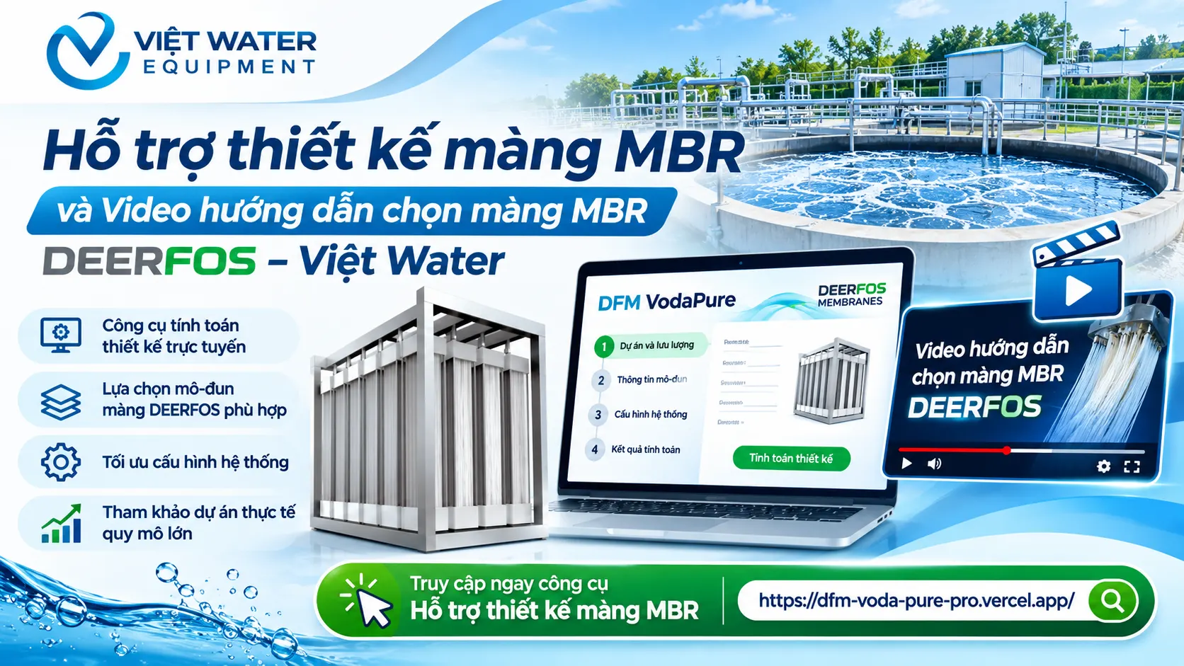
DFM VodaPure is the tool featured in the MBR membrane design tutorial video provided by Viet Water. The video interface shows several main working areas, including project and flow information, membrane module details, system configuration, and calculation results.
The tool helps users approach membrane selection systematically using project parameters rather than estimating the number of modules alone.
Enter project identification and wastewater flow information.
Select DEERFOS membrane module models from the available list.
Configure the membrane system.
Review preliminary calculation results and membrane arrangement information.
Use the results as a basis for further technical design review.
Please note that the tool's output should be treated as a preliminary design reference. Before equipment procurement or installation, engineers should verify membrane specifications, operating limits, and actual site conditions.
The supplied video is approximately 1 minute and 49 seconds long. It demonstrates the DFM VodaPure interface, from entering initial information to viewing the calculation results.
The video focuses on operating the tool. Users should prepare their design flow rate, project information, and membrane configuration requirements before following the tutorial.
Open the tool and follow along: https://dfm-voda-pure-pro.vercel.app/
Website publishing note: Upload the instructional video to your website server or video hosting platform and embed it directly into the article. The link above points to the design application, not to a playable video.
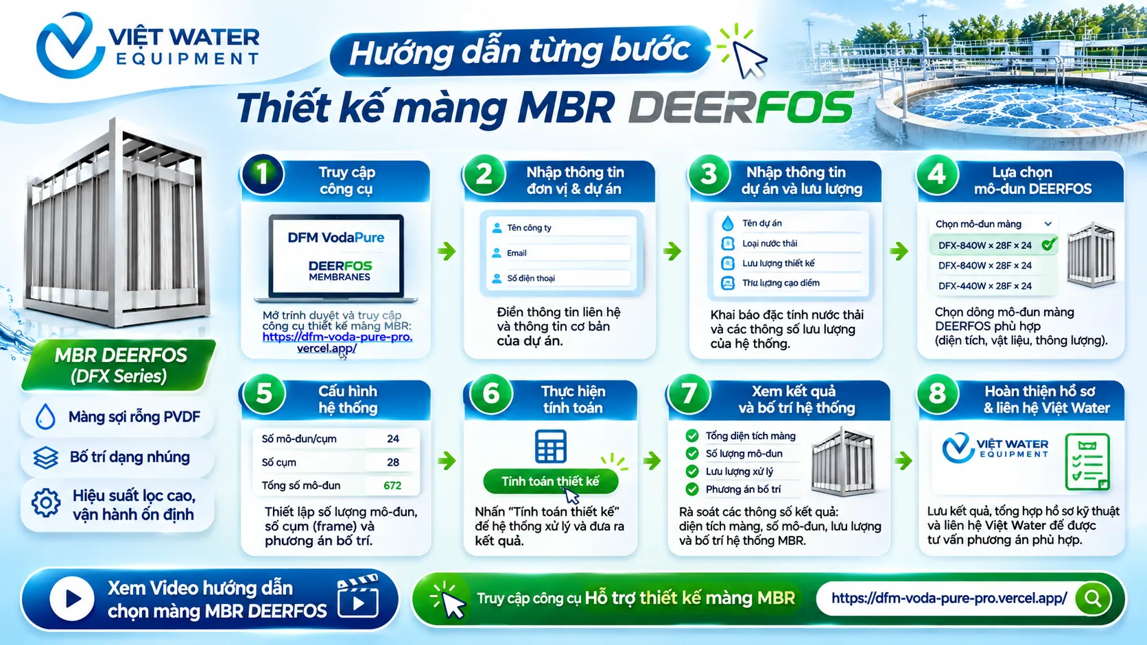
The following procedure explains the workflow shown in the supplied tutorial video.
Open a web browser on your computer and visit:
https://dfm-voda-pure-pro.vercel.app/
The initial interface displays the DEERFOS brand and DFM VodaPure. The video shows users entering preliminary information before proceeding to the main design interface.
If the application requests registration or contact details, complete the fields displayed on the screen. Do not use fabricated information or data from another project without authorization.
At the beginning of the video, the form displays contact fields such as company name, email address, and telephone number.
Prepare the following information:
Company or project organization name.
Contact email address.
Telephone number.
Any additional information requested by the application.
After completing the form, follow the on-screen instructions to continue to the design interface.
For Viet Water customers, using the contact details of the responsible project representative can help organize technical records and facilitate follow-up discussions.
After entering the main interface, the video shows a section labeled Project and Flow, where users enter information related to the wastewater treatment facility.
For an actual design project, prepare the following data:
| Parameter | Description |
|---|---|
| Project name | Name of the plant or facility |
| Wastewater type | Description of the wastewater source and characteristics |
| Design flow rate | Wastewater volume to be treated under design conditions |
| Peak flow rate | Data used to evaluate capacity during high-flow periods |
| Operating hours | Actual operating hours per day |
Important: Verify the fields and units against the live application interface. Do not enter a daily flow rate into a field that requires an hourly flow rate, or vice versa.
For example, if a plant generates 1,000 m³/day and operates continuously for 24 hours per day, the average flow rate is:
1,000 ÷ 24 = 41.67 m³/hour.
This is only a conversion to average hourly flow. Actual membrane design must also account for hourly fluctuations, peak flow, and system downtime.
The video shows a Module Information section containing a membrane model selection list. Users can open the list to review the module models available in the tool.
When selecting a module, check the following technical specifications:
Exact product model.
Effective membrane area per module.
Membrane structure and material.
Manufacturer-recommended design flux.
Operating limits and aeration requirements.
Membrane cleaning, maintenance, and replacement requirements.
Do not select a module based solely on its model name or membrane area. Modules with similar membrane areas may have different operating conditions and technical requirements.
Viet Water recommendation: Verify the selected model against the official DEERFOS catalogue and technical documentation before finalizing the design.
The video then shows a System Configuration section containing fields related to the number of frames or module groups and the overall system arrangement.
At this stage, review the following items:
Planned number of membrane modules.
Number of modules per frame or assembly, according to the application's configuration structure.
Total number of assemblies required.
Available space inside the membrane tank.
Clearance for aeration equipment and piping.
Access for lifting, cleaning, maintenance, and module replacement.
For an actual project, the number of modules must match the required membrane area and installation configuration. Adequate operating and maintenance space must also be provided rather than simply maximizing the number of modules inside the tank.
After entering the required information, use the calculation function displayed in the application.
According to the video, the tool proceeds to a calculation results section that presents summary indicators and information related to the membrane configuration.
Review the following items:
Confirm that the input flow rate is correct.
Verify the selected membrane module model.
Check that the membrane area and module quantity are consistent with the configuration.
Confirm that the results are appropriate for the required flow rate.
Review any warnings or operating limitations displayed by the application.
If the results appear unusual, check the units, flow rate, and configuration before running the calculation again.
After calculation, the video displays a Calculation Results section and information about the MBR membrane arrangement.
Record the relevant results for further technical review, including:
Input design flow rate.
Membrane module model and membrane area.
Total membrane area.
Total number of modules and frame configuration.
System arrangement parameters provided by the application.
Verify these results against the membrane tank drawings, piping layout, and project operating requirements. A preliminary calculation should not be treated as a complete construction design without review by qualified engineers.
After obtaining the preliminary results, compile the input data and calculation outputs for further technical evaluation.
The design package should include:
Project information and design flow rate.
Wastewater quality analysis.
Proposed membrane model.
Total membrane area and module quantity.
Tank dimensions and layout drawings, if available.
Treated water quality requirements.
Operating conditions and maintenance requirements.
Viet Water can receive the project information and discuss equipment requirements and suitable technical options within the company's service scope.

A design tool can simplify preliminary calculations, but the quality of the final solution still depends on the input data and technical verification.
Distinguish between average flow, peak flow, and design flow. If part of the system must be taken offline for maintenance, the design should also consider whether the remaining equipment can meet treatment requirements.
Parameters such as BOD, COD, TSS, nitrogen, phosphorus, pH, and other specific contaminants affect biological treatment, pretreatment requirements, and membrane operating conditions.
Wastewater containing oil and grease, fibers, large solids, or substances that cause membrane fouling may require appropriate pretreatment.
The required membrane area should be calculated based on the design flow rate and a suitable membrane flux, taking into account wastewater characteristics, operating conditions, and manufacturer recommendations.
A single fixed flux should not be applied to every MBR project.
The MBR membrane is only one component of the treatment process. The design must also consider the biological tank, aeration system, suction pumps, piping, controls, and membrane cleaning procedures.
In particular, achieving nitrogen, phosphorus, and dissolved organic matter targets depends on the biological treatment process and any supplementary treatment stages.
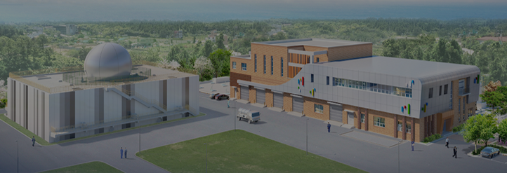
To illustrate the application of MBR technology in a large-scale facility, Viet Water presents information from the supplied project document for the Myeonghak General Industrial Complex Wastewater Treatment Plant in Sejong, South Korea.
The facility uses a submerged DEERFOS PVDF hollow-fiber membrane system to treat wastewater generated by semiconductor substrate and battery manufacturing.
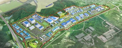
Project: Myeonghak General Industrial Complex Wastewater Treatment Plant.
Location: 697 Myeonghak-ri, Yeondong-myeon, Sejong, South Korea.
Wastewater source: Semiconductor substrate and battery manufacturing.
Installation date: August 2025.
Technology: Submerged DEERFOS PVDF hollow-fiber membranes.
Product model: DFX-840W × 28F × 24 SET.
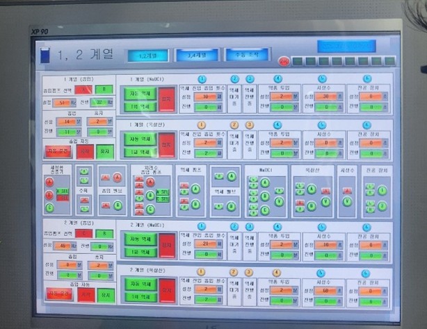
According to the supplied project document, the system has the following specifications:
| Parameter | Value |
|---|---|
| Membrane area per module | 40 m² |
| Number of modules | 672 |
| Total membrane area | 26,880 m² |
| Design flow rate | 8,000 m³/day |
| Maximum flow rate | 13,440 m³/day |
These figures illustrate the relationship between membrane area, module quantity, and treatment capacity in a large wastewater treatment facility.
This configuration should not be directly applied to another project without evaluating wastewater characteristics, design flux, and actual operating conditions.
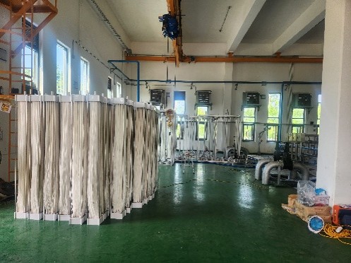
The project document highlights the following design considerations:
Integration with the biological tank and existing treatment system.
Maintenance planning by equipment group.
Partial module replacement capability.
Modular construction to improve maintenance efficiency.
Optimized membrane arrangement within the existing facility.
Reinforced PVDF membranes to improve durability and filtration performance.
These considerations are useful when evaluating MBR systems for industrial facilities that require reliable operation and efficient use of available space.
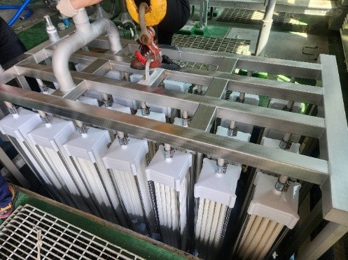
The supplied project document lists the following influent values and treatment targets:
| Parameter | Influent | Target |
|---|---|---|
| BOD | 142 ppm | ≤ 5 ppm |
| COD | 115 ppm | ≤ 20 ppm |
| TOC | 105 ppm | ≤ 7 ppm |
| SS | 115 ppm | ≤ 10 ppm |
| T-N | 34 ppm | ≤ 15 ppm |
| T-P | 3.8 ppm | ≤ 0.3 ppm |
These values represent targets stated in the project document, not independently verified effluent monitoring results. Actual performance depends on the complete treatment process and operating conditions.
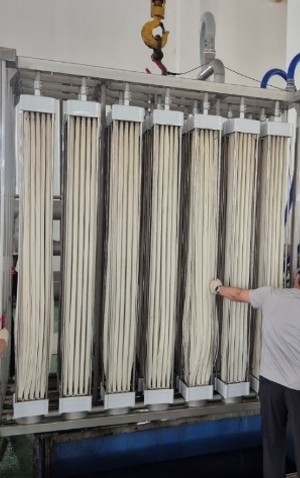
The Myeonghak project provides several useful considerations for project owners and system designers.
Optimize installation space: Evaluate total membrane area, module configuration, and maintenance access to select an arrangement suitable for the available footprint.
Design for maintenance: Grouping equipment and enabling partial replacement can improve maintenance planning and operational flexibility.
Design around effluent requirements: The MBR membrane must work with the biological treatment process and appropriate supplementary treatment stages to achieve the required water quality.
The Myeonghak project is presented as a reference for DEERFOS technology application. The supplied document does not establish that Viet Water directly executed the project in South Korea.
The tool can be useful during preliminary planning and design evaluation for projects involving:
New wastewater treatment system design.
Upgrading or modifying an existing MBR system.
Comparing membrane configurations and module quantities.
Preparing technical information for equipment suppliers.
Preliminary assessment of membrane installation within an existing tank.
Initial equipment planning and cost estimation.
Facilities with complex wastewater characteristics, significant flow fluctuations, or stringent effluent requirements may need additional engineering assessments before finalizing the configuration.
VIET WATER EQUIPMENT CO., LTD. supports customers in evaluating water treatment equipment and discussing MBR membrane solutions based on project requirements.
If your organization is planning a membrane configuration, selecting DEERFOS modules, or evaluating an upgrade to an existing wastewater treatment system, prepare your flow data, wastewater quality analysis, and facility drawings for a more productive technical discussion.
Access the design tool today:
MBR Membrane Design Support – DFM VodaPure
VIET WATER EQUIPMENT CO., LTD.
Tax ID: 0318681463
Address: 345 Pham Van Bach Street, Ward 15, Tan Binh District, Ho Chi Minh City, Vietnam.
Telephone: (+84) 028.6272.4888 – 0947.9999.30 – 0904.506.065
Email: eqvietwater@gmail.com
MBR Membrane Design Support with Viet Water – Calculate, select DEERFOS membrane modules, and develop wastewater treatment solutions tailored to your project requirements.
Viet Water is one of the reputable units, located at 339 Pham Van Bach, Ward 15, Tan Binh District, Ho Chi Minh City. With tax code 0312931928, the company provides Deerfos MBR membrane filters, committed to ensuring quality and reasonable prices.

Màng lọc UF Deerfos (Korea) đại diện cho sự tiên tiến trong công nghệ lọc nước, với thiết kế nhỏ gọn, dễ dàng lắp đặt và vận hành, cùng tuổi thọ cao. Sản phẩm này đáp ứng nhu cầu xử lý nước sạch và tái sử dụng nước thải hiệu quả, mang lại lợi ích không chỉ cho môi trường mà còn cho sức khỏe con người.

Hệ thống xử lý nước thải màng lọc MBR 2000 m³/day từ Việt Water – Công nghệ hiện đại, tiết kiệm diện tích, nước đầu ra đạt QCVN.

Viet Water Equipment provides GFS Glass-Fused-to-Steel tanks compliant with AWWA and NSF/ANSI 61 standards, over 30 years lifespan, fast installation, and cost-effective solutions for clean water and wastewater projects.


